The Trinity College International Fire Fighting Robot Contest is a yearly event where robots are tasked with navigating a simple maze and extinguishing a candle somewhere within as quickly as possible. On April 12th I flew up to Hartford, Connecticut to compete with my robot Pyrobot.
The PyroBot in this picture is very different from the robot I planned to build. I had high hopes for PyroBot, but as usual everything is twice as hard as you think it will be and takes twice as long as you think it should. Despite the setbacks, I am happy with the project as I was able to pull off a small victory in the end.
The Rules
I won’t go into too much detail, but the gist is that you are allowed to do five total runs of your robot in three levels of increasing difficulty. You may only attempt a harder level once you have completed the one before it. You get 600 points for each level you don’t complete (unlike in baseball, lower scores are better). Your total final score is the sum of your best scores on each level. Level 1 is the most simple: you know where all the walls will be and the only obstacle is a stuffed animal randomly placed at one of three possible locations. Level 2 adds carpets, multiple wall configurations, and “decorations” on some of the walls (ie. mirrors and fabric). In Level 3 the two mazes are combined and start you randomly in the first. The goal is two blow out three candles in the second maze as well “rescue a baby” (move a doll from the second maze to the first).
The Plan
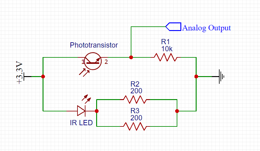
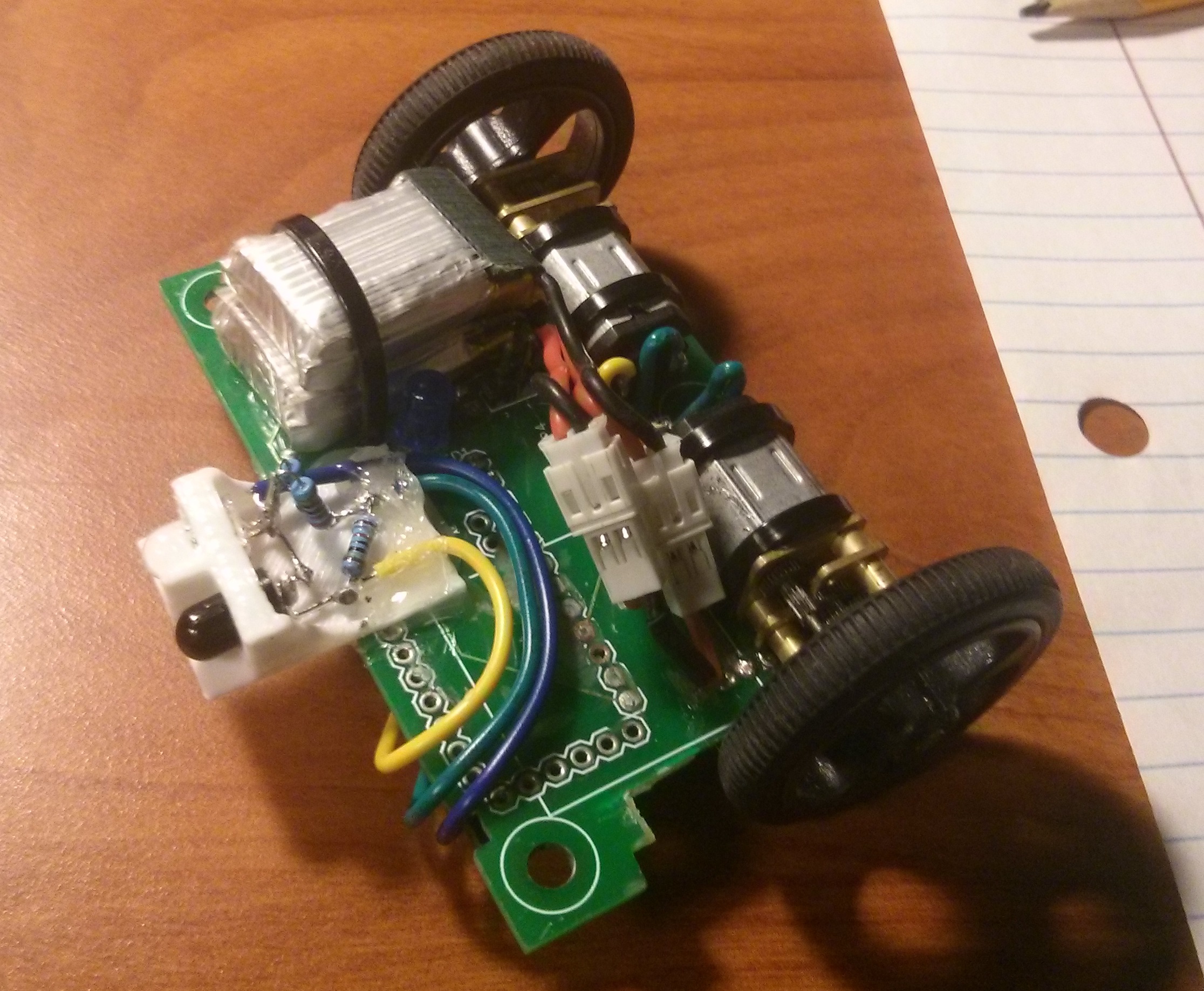
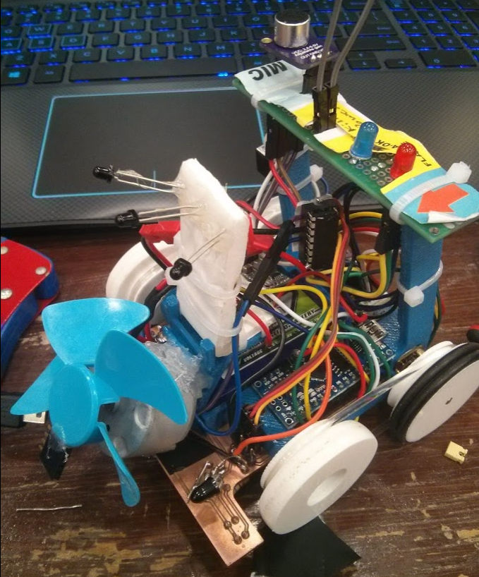
My friend Kaiz and I began work on our strategy over 2 months ago. At first, the plan was to do almost everything and do it in the style of a MicroMouse robot. We noticed that most of the robots at past competitions were relatively slow (except for this bot from China, by far) but even the fastest robot didn’t compare to the speed of a MicroMouse. I splurged on some of the expensive IR LEDs (sfh4545) and phototransistors (teft4300) used by many MicroMice for distance sensing. The go-to motors for MicroMice were a bit out of my price range so I went with some aggressively geared N20 motors that had integrated encoders. The Motors were driven by a chip I am very familiar with, an L293D Dual H-Bridge. There is really no limit on what fan you are allowed to use to blow out the candle, so I chose to use the BLDC motor off of an RC plane I once built. Next, I chose the battery. After some testing with a 7.4V (2 cell) battery I wasn’t happy with the speed of the robot, so I decided to use a 11.1V (3 cell) battery instead, which also improved our fan performance. To control the robot I considered using an ESP32, but ultimately went with an Arduino Nano because of its size and my previous experience with the board. Again inspired by MicroMice, I chose to make the chassis of the robot a custom milled circuit board, fabricated on an OtherMill at (NC State’s ECE Maker Space)[https://my.ece.ncsu.edu/makerspace/]. Finally, we figured finding the candle was a great vision processing task and planned to use Kaiz’s JeVois vision processing camera with an IR pass filter. After carefully designing the 3D printed parts and circuit board and tediously soldering some wires, we thought we had the hardest problems solved.
The Problems
The Nanos
I figured from the start it would take two iterations to design the circuit board: an initial prototype and a final product with all the kinks worked out. However, when I was designing the robot I made a fatal error. In order to save space, I hung the Nano underneath the robot where there was not enough vertical space for female headers, meaning that I soldered the Nano directly to the circuit board. This had the awful side effect that if we ever fried a Nano, we had to replace the entire chassis. You may think I’m stupid for even attempting a strategy like that, but in my defense it has worked great for me before on one of my combat robots. The difference between that project and this one is the combat robot was less complex and ran on much less than 12 volts. After 3 bricked chassis I gave up on the hanging method and moved the Nano to the top of the board with female headers. This ended up being the right choice by far as I only fried 2 more Nanos during development that I was able to “hot-swap” out. Unfortunately, by the time I made this switch we had lost 5 days (milling these boards is difficult) and I only had time to make a first iteration of the “hot-swap” design.
Voltage regulation
I fried the third Nano by supplying 12V to VIN. The documentation says that Nanos can run off of 12V but I looked into it and it seems that the 5V linear voltage regulators on Chinese clones can handle only around 7V to 10V. It was at this point I said “screw it” and added not one but three switch mode regulators to the robot: a 7.5V regulator to keep the Nano happy, a 5V regulator for the JeVois as it could draw up to 1A, and a 3V reg for the IR LEDs. I was going to power the LEDs off of the Nanos 3.3V line, but they too draw a decent amount of current and I wanted to reduce the strain on the Nano as much as possible.
The Boards
On top of the strategic errors surrounding the custom boards, the boards themselves were of poor quality and caused many issues. It was a pain to design them because any jump from one side of the board to the other has to be connected through vias. For example, all of the Arduino headers could only be soldered/accessed on the bottom of the board. The most common physical issue was a trace breaking (or in some cases frying), which meant I would have to run a wire to jump the connection. The worst issue resulted in me at one point ripping about 6 pads off of one section of the board and doing some very janky wiring to fix it.
The JeVois
If the other issues were thumb tacks, this issue was a train spike in the coffin. We only got the robot fully together a couple of days before the competition. At this point we knew we couldn’t “do everything”, but we at least felt like we could still be competitive.
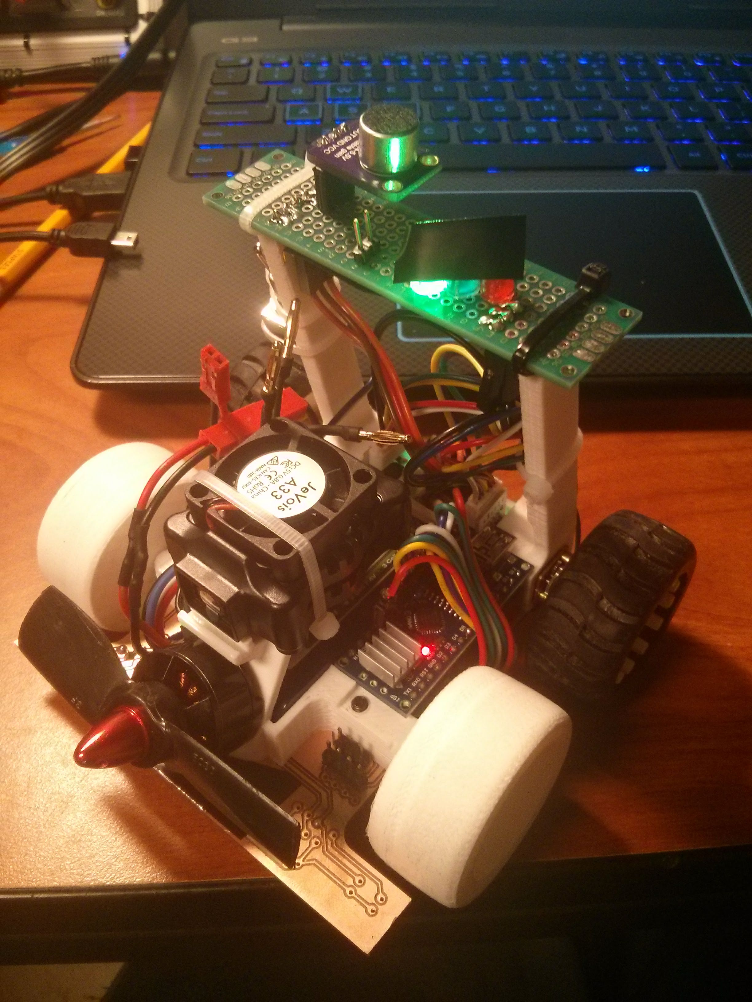
It was then that I had to drop the JeVois. While Kaiz could get it to find the candle excellently when plugged into his laptop, we could not for the life of us get it to spit any of its data out over serial. We worked on this issue till 4:00 AM the night before my flight and to this day we don’t know what the problem was. I flew into Hartford with a robot that could barely navigate a maze and not only had never seen a candle before, but at that point was entirely blind.
The Bodge
Hardware
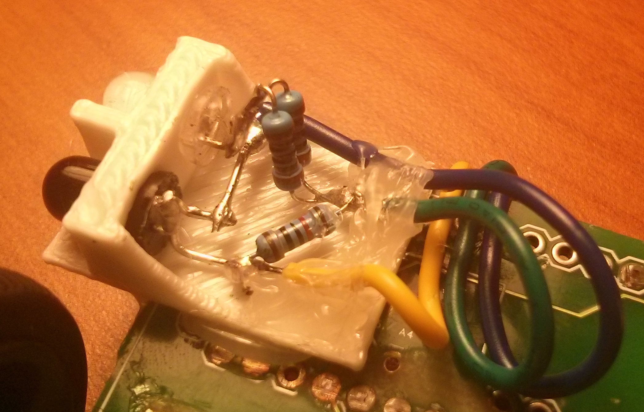
When I started this project I pictured rolling up to Hartford with a beautiful well-crafted robot that was basically a Micromouse with a fan on it. I’m very much a perfectionist; the robot would be a perfectly programmed, meticulously designed, and well-crafted machine. On Friday night a switch flipped in my head and my mentality changed. I couldn’t let perfect be the enemy of good and I just wanted to have the robot work at all. There were minor electrical issues to fix but the main issue was finding and pointing towards the candle. At the hotel I cannibalized some of the IR distance sensors off of the front of the robot and repurposed their phototransistors to instead look for the candle. I arrived at the competition site at 7:15 and was the first person inside the venue. After I set up my pit I spent the next 4 hours fixing minor electrical issues and preparing my robot to be inspected before noon. I knew the bot I had built was small, but at the inspection table, I was told my bot was one of the smallest the inspectors had ever seen. I realized that if I could just complete a single run, I would likely win the tiny robot contest, doing so became my primary and only goal.
Software
By 1:00 PM I was feeling good about my progress. Thereafter minor electrical issues sporadically popped up, but I was able to turn most of my attention to the software. I had to throw out a lot of the code I brought with me. Kaiz and I originally planned to move through the maze using a PID based planned path, but now that I didn’t care about my score and time was a huge issue I changed my approach to that of a blind search. My strategy had 3 parts:
- A simple right wall following PID loop using the robots front right distance sensor (this worked well because if the right wall ever “fell away” the robot would turn sharply right)
- The robot used its last remaining forward facing distance sensor to check if it was about to run into a wall. If a wall was detected it would back up, turn 90 degrees left, and continue to follow the wall.
- The robot would periodically turn off its IR LEDs and look for IR light. If it detected light above a threshold it knew the candle was nearby, at that point the main loop was done and the robot just had to blow out the candle.
The first Item on this list was the most difficult to implement. I spent a good amount of time trying to tune parts of my PID loop: the terms, the max speed, and the output limits. After a while, I got a legendary suggestion from one of the other competitors:rotate the sensor 45 degrees forward. I rotated the sensor and increased my setpoint, it was like magic. It followed the wall and turned right when the right wall fell away on the first try. I still tuned the PID a bit more but for me it was a small victory after a long list of failures. After that, the front wall detection got working in no time, here is the robot with the two behaviors combined.
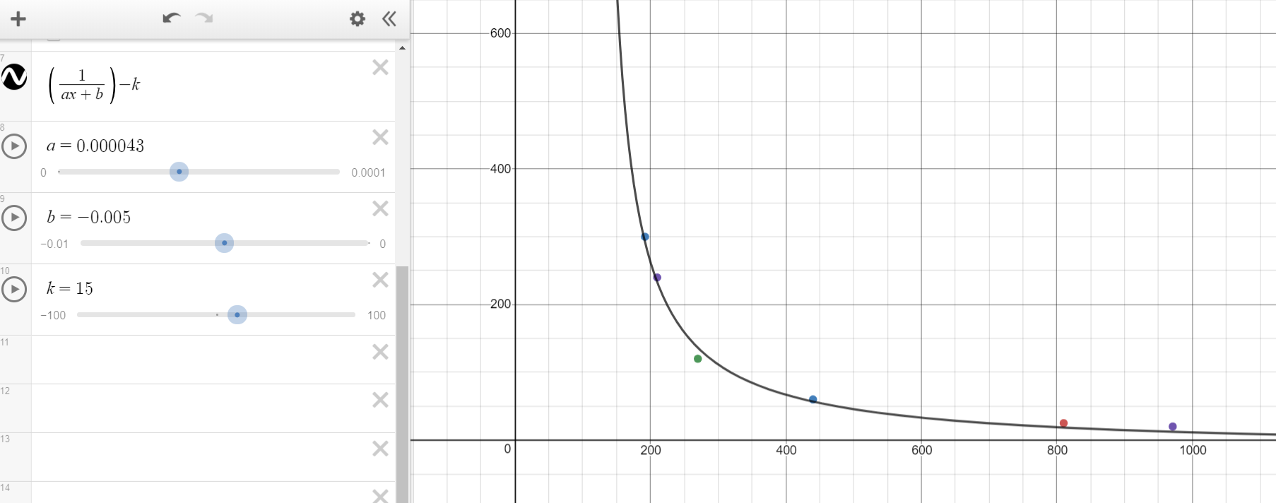
The third part of my strategy worked quickly as well. Using the three phototransistors the robot could reliably find and even point at the candle. The main issue was the robot had a hard time knowing how far away from the candle it was. I never came up with a cool solution to that problem, I just programmed it to drive forward and backward until the candle was out.
The last big hurdle
By 4:00 on Saturday I was feeling good but still nervous, because if I didn’t attempt my first two runs by 5:15 they both would be recorded as DNFs. I was all set to do a couple more practice runs and then head to the competition fields when I got hit with a final terrible problem, my BLDC motor wouldn’t spin! I spent the next hour and 15 minutes trying different PWM signals, eliminating any potential mechanical issues and I even swapped out the ESC but it never got up to speed. I lost the chance to attempt 2 of my 5 runs and left the event for the day.
Sunday
Sunday was crunch time. I gave up on the BLDC motor and resolved to use a different motor I brought, an impeller fan. I cannibalized a spare L293D into basically a MOSFET and tacked on the fan with hot glue. I had more success than with the BLDC motor (including my first successful unassisted practice run) but it was not very powerful and not reliable at all. I ended up borrowing a motor and broken fan from another team. I added a “counterweight” to fix the broken fan and that was the last big problem solved. From then on I was just testing and tuning. For me that was the most fun I had; all that remained was tweaking IR thresholds, time delays, and PID values until I was satisfied with my robots consistency. By 1:00 PM I was ready for my first run
Attempt 1
I’ll cut to the chase, it worked! Lucky for me the candle was in the first room PyroBot looked inside (although at that point the robot could search almost the entire maze). It wasn’t a thrilling run, but I was stoked. For me, it was incredible to clobber together a clutch success when not 48 hours ago the robot was blind and had no code. This also meant that I basically had the tiny robot award in the bag. I foolishly forget to record the run, but afterward, I recorded a recreation with the same starting conditions.
Attempts 2 and 3
I didn’t make any changes for my second run, now in level 2. The run failed because the robot got stuck on the carpets. The drivetrain was already geared to be high speed and low torque, but on top of that I was running the drivetrain at no more than 40% of its max speed. I bumped the drivetrain up to 60% power, but this messed up my PID and turn left function. I re-tuned both parts of the control logic but didn’t have the time to thoroughly test it. In my third and final attempt, PyroBot had no problems with the carpets, but it ended up getting stuck in one of the rooms and failing the attempt.
Closing Ceremonies
In the end, I did receive the Tiny Robot Award, but what I didn’t expect was to be the Honorable Mention for the Spirit of the Inventor Award. The guys that won it really deserved it. They built an autonomous drone that could navigate the maze, it was very cool. In the end, I was very happy with the trip. On one hand, I flew all the way to Connecticut to blow out a single candle, but on the other, I learned a lot, met a ton of cool people, and I will definitely be back next year (and maybe I will start a bit earlier ;p).
Side note
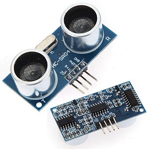
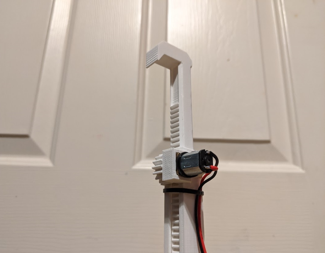
There was one part of the robot that doesn’t fit anywhere in this blog, but I feel like I should include. It is mandated by the rules that each robot must be able to detect a 3.8kHz ‘start tone’ to start its run. This was maybe the most reliable part of my robot, but other teams struggled with it. I used a mic (WITH AN AMP) along with a Fourier transform library built for Arduino to detect the 3.8kHz tone. It took maybe an hour to tune the thresholds but I never had a false positive or a false negative.
]]>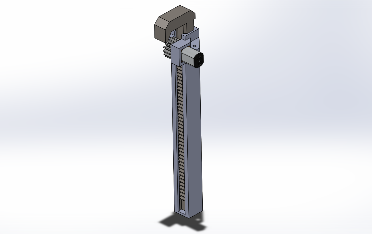
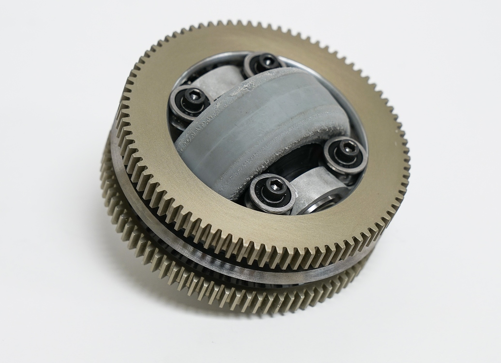
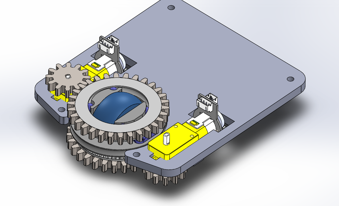 We didn’t end up using it in MiniFRC 5 because the modules are quite large, it would have been too much to try to fit even 3 modules within the frame limit, let alone other robot mechanisms. I plan to one day build a 3 module drivetrain. But until then I will go ahead and post the CAD here.